This post is older than 2 years and might not be relevant anymore
More Info: Consider searching for newer posts

Instructions for setting up 9160 DK for current measurement are confusing

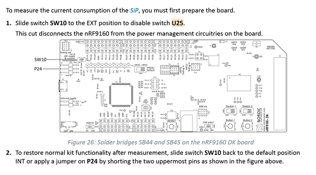
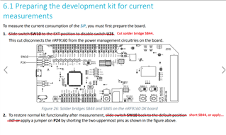
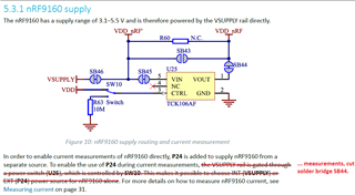
I looked at the nRF91_DK_User_Guide and it is very confusing to understand how to set up the board for current measurements. The figure says to solder SB44 and SB45 but the text doesn't. In fact, the text refers to the figure talking about shorting P24, which the figure does not illustrate. If I switch SW10 to Ext and I supply 5V on P28 it doesn't work at all. If I switch SW10 to Int but I provide power using P28 the system does work. Should I be shorting SB44 and SB45? I think the documentation needs to be improved here.

Parents Reply Children
  • Update: This answer is valid for nRF91 DK v0.7.0, v0.8.2, v0.8.3 & v0.8.4. Not valid with the latest v0.8.5 nRF91 DK! There is a bug in the user guide v0.7. Without SB44 cut, the U25 switch leaks current, which could lead to the high current readings. It should look like this:

    You will need to cut the SB44 on the nRF91DK. This will disable switch U25 & therefore it does not matter which position SW10 is in.

    "Measuring current using the DK guide setup will give bad results. The switch (U25) leaks current from VOUT to GND even when off.

    Pin closest to USB connector is pin3
    1. Measure current using an ammeter: Connect to pins 1 and 2
    2. Measure current using a supply like Agilent 6705: Connect to pins 1 and 3.
    3. Accidentally shorting pins 2 and 3 -> dead DK! So be careful, remove USB power before connecting your measurement probes.

    To make the board work again using USB power only, short pins 1 and 2."

    Summary:

    Flash the secure boot & the app to the nRF91 via usb, remove the usb cable, then cut the SB44 & power the board via a PSU on connector P24. SW10 can be in either position (it makes no difference when SB44 is cut). To restore normal kit operations (e.g. erasing & programming the SiP), put a jumper on the two uppermost pins of P24.

    Kind Regards,

    Bjørn

  • my board does not have Sw10. It is version 0.7.0

    how to measure in this case ?

  • The answer I posted should be valid for v0.7.0 too. As posted in the answer, switch 10 is not needed for current measurement.

  • Hi,

    I have v0.8.5 nRF91 DK. For what i've undertood, this answer is not valid for my DK? How do I have to set up my board to make the current measurements?

    the latest user guide I found is for the v0.7.1, i haven't found the documentation for the v0.8.5, is there any newer documentation?

    Thanks!

  • Hi Bjørn,

    How can I measure the current consumption by the module during different phases (uplink payload data transmission, during the inactivity timer duration, ..etc) using the above method?

    The version of my kit is 0.8.2.

    Regards,

    Ahmed

Related